I was working on a project that required an HD44780 LCD. The arduino LiquidCrystal library makes it very easy to interact with it. But one major problem with using the arduino with this LCD is that it consumes at least 7 IO digital pins (that's half of the Duemilanove digital pins) and if you want to use the lcd in 8bit mode you will need 11 pins! That makes it almost impratical of using the lcd in 8bit mode.
An easy solution is to feed the data using a shift register. That way we will only need 1 pin to feed the data and not 4 (or 8). Additionally, using the shift register, we can release yet another pin, I'll explain that latter.
So, I connect the shift register to the data pins of the lcd, rewrote the LiquidCrystal library and started to use the lcd with the shift register, but a new problem arose. There were lot's of wires in my breadboard and almost no space for doing the "real thing". And so the idea of doing a LCD shield came out.
The LCD Shield
FAQ
What is the LCD Shield?
- I's a board that sits on top of the arduino board and has a lcd display that only uses 3 pins of the arduino (4 if you want to control the contrast of the lcd with the arduino).
What changes do I need to do to my arduino project for that to work?
-Nothing, you will only need to use the modified LiquidCrystal library in you projects.
How it works
Now that all the questions were answered, let's start explaining how it works. To control the hd44780 you have 3 pins: the enable(en), the instruction/data selector(rs) and the read/write (rw). The rw it's used for checking if the lcd is busy, I found that it's not really that necessary, and since I'm in a pin budget I will release it from the arduino control and set it only to write mode.
So, to 2 pins are needed to control the lcd. For the shift register we need 2 pins also, one for the clock and one for the input. But we can use the same pin for the rs and the data input, because we feed the data and then set the rs pin. The final pin count is 3 pins, in 8bit mode.
Additionally I added 2 jumpers and 1 pot to the circuit. The first jumper gives the possibility to use a pwm pin of the arduino to control the contrast (the digital pin number 11), the second jumper selects if the back light is controlled by the pot on the board or not.
The hardware
To build the shield you'll need a PCB board to print the layout, a 8bit shift register (I'm using the 74LS164N), some male and female connectors, a pot, and of course a HD44780 compatible lcd. Also, you'll need solder, an iron and some ironing skill.
The prototype
I build one prototype to see how(if) it works. It's been a long time since I've made a PCB and I considered ordering one, but for one piece only is very expensive so I tried to make one like this, using a glossy paper and a laser printer.
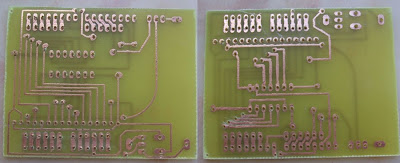
In my design I mounted the shift register and the male connectors in one side of the board and the lcd, pot, jumpers and female connector on the other side. Since I am not capable of doing plated thru holes I used vias. The only tricky part is the vias between the male and female connectors, they are very very close. I have the pcb files for a non plated thru holes version of the board and a plated thru holes version board.
And here is the result, after etching and drilling.

And with all components soldered.
 The files
Finally the files you are all asking for.
The pcb design was created using Eagle and you can download the project files here.
And the LiquidCrystal can be found here.
The LiquidCrystal Library
This library is based in the LiquidCrystal library found on the arduino official page. The difference is that now it supports the serial mode also.
So, I added 2 constructors:
- one with 3 parameters - LiquidCrystal(uint8_t enable, uint8_t clk, uint8_t data_rs)
- and one with no parameters. - LiquidCrystal()
If you have any doubts, suggestions, critics, etc feel free to contact me.
And if you want an LcdShield contact me, I'm planning to send the project to a PCB manufacturer and produce some boards.
TVeiga
